
Multi-channel array, two halves
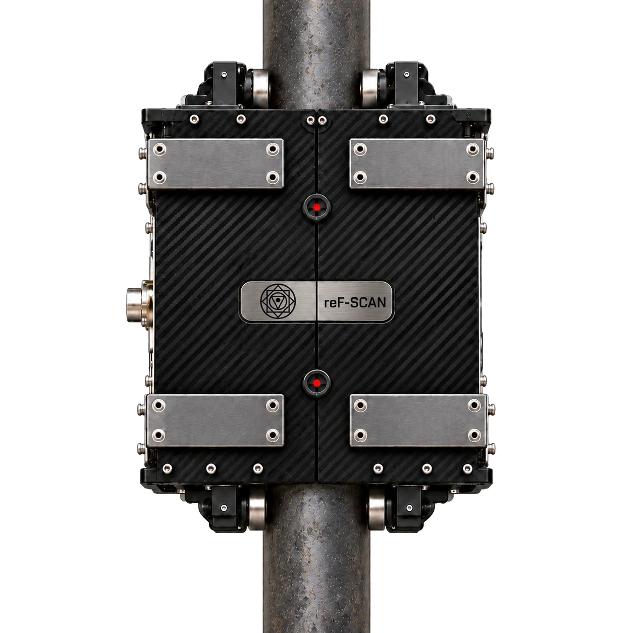
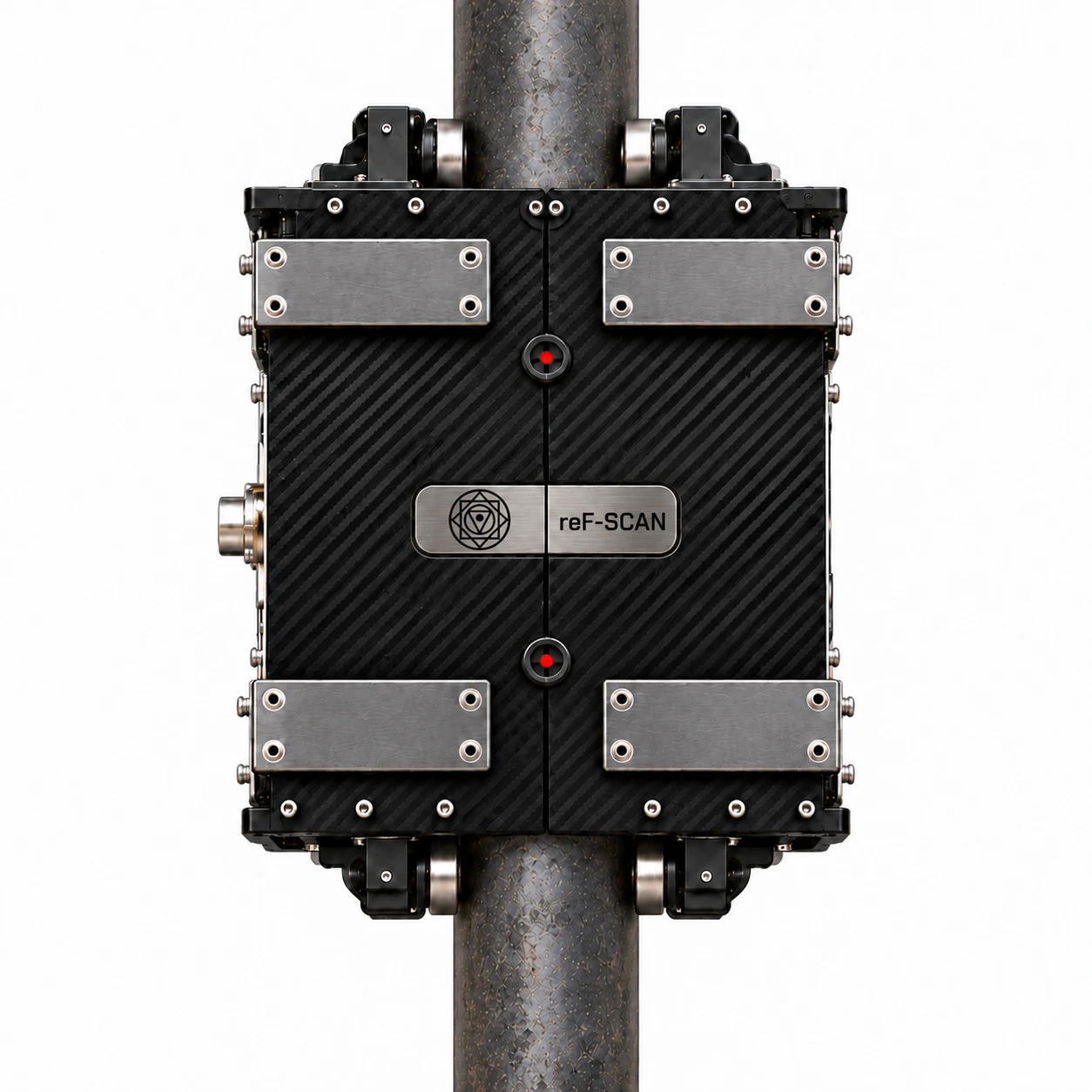
Two probe halves clamp around the tube, each covering 180°.
360° cracker coil intelligence
reF-SCAN is NDT Technologies’ indigenously developed robotic crawler for ethylene cracker radiant coil inspection. Its multi-channel TFET array scans the full 360° of the tube wall from the outside, and the same pass captures laser OD growth, gyroscope bowing data and HD visual evidence.
Asset challenge
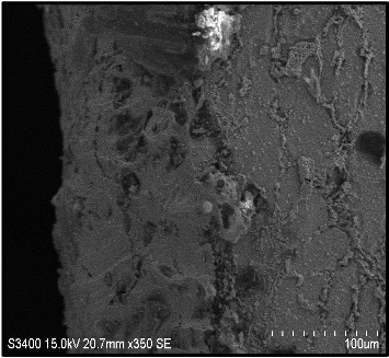
Ethylene radiant coils are centrifugally cast HP-type alloys running at some of the highest metal temperatures in the plant. Their as-cast structure — an austenitic matrix with interdendritic carbide networks — changes in service: secondary carbides precipitate and coarsen, and creep cavities nucleate. Carbon from the coke layer diffuses inward, consuming chromium and leaving a depleted, magnetically altered matrix. Decoking cycles add inner-wall decarburization and micro-fissuring. Each of these begins at microstructural scale, long before bulging or cracking becomes visible.
Heat flux, coke thickness and flame proximity vary around each tube. Carburization therefore starts and grows at circumferential positions that cannot be predicted in advance — fire side, side wall or back side — and it begins at the inner wall, out of sight of visual and surface methods.
Inspection architecture
Select an evidence layer to see how it contributes to the inspection decision.
Transition Field Electromagnetic Technique (Indian Patent No. 550047) responds to microstructural change in centrifugally cast cracker tubes — carbide precipitation and coarsening, creep cavitation, carburization-driven chromium depletion and inner-wall micro-fissuring. Exciter and detector coils sit on the OD and the field passes through the full wall, giving high sensitivity to micro-damage originating at the ID. The multi-channel array covers the complete circumference, so no sector of the tube goes unread.
All four streams are captured in a single crawler pass, position-matched along the tube.
360° coverage
The reF-SCAN TFET probe is a multi-channel array built in two halves that close around the tube, each covering 180°. Together they read the full circumference continuously as the crawler travels the radiant pass. Wherever carburization or ID micro-damage has started — fire side, side wall or back side — it falls under a channel.
Two probe halves clamp around the tube, each covering 180°.
Results are plotted as an unrolled tube map: position around the tube against distance along it.
Each indication is reported with its position around the tube and its length along it.
| Partial-circumference scan | reF-SCAN 360° |
|---|---|
| Reads only the sectors it covers | Reads the full circumference |
| A localized carburized zone outside the scanned sector is not seen | A localized zone at any angle is detected and located |
| No measure of how far damage has spread around the tube | Circumferential spread and axial length are both reported |
Assessment & decision
Every tube scanned receives a TFET severity grade, read together with the circumferential spread and axial length of the indication. Grading is calibrated against metallurgical examination of in-service tubes. Repeating the scan at each turnaround tracks how every tube’s condition progresses — a tube-by-tube basis for replacement planning and safe continued operation.
Field evidence
Imagery from NDT Technologies inspection material, presented as an evidence-led sequence. Client names and identifiers are removed.
Engineering outcomes
The value is not the sensor alone — it is the coverage and usability of the evidence it produces.
360° TFET coverage finds carburization wherever it starts around the tube, not only where a probe happened to be placed.
Through-wall TFET picks up micro-fissuring, decarburization and carburization that begin at the inner wall, using OD access only.
TFET reduces dependence on highly cleaned tube surfaces, shortening preparation inside a tight turnaround window.
Repeat scans on the same grading basis show how each tube’s condition progresses, so replacements are planned rather than forced.
Discuss your radiant coil inspection scope with our team.